2. The platform
What makes reality hard, and the platform that solves it
From a simulator to the platform
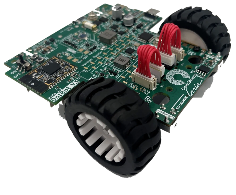
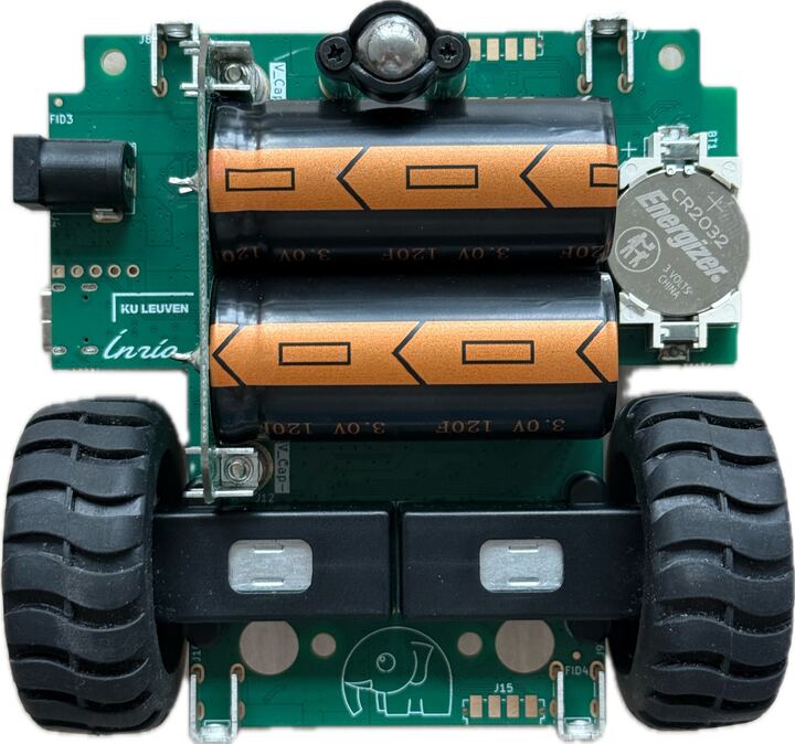
The bridge slide “From simulator to reality” asks how hard it can be to go from a swarm in a simulator, which you start yourself in step 3, to real robots on the floor. Then the instructor presents the platform that makes it possible: the robot, how it finds its position, how it talks, how it gets new programs, and the software you drive it with. It starts with the robot itself, in Figure 1.
The pillars
Each one names the problem it solves, and links to its paper on the references page.
- The robot, DotBot v3: low cost, and a charge in seconds. ICRA 2024 workshop
- Lighthouse 2, each robot’s position: low cost, and it scales, since each robot computes its own position on board. IEEE RA-L 2024, calibration, IEEE RA-L 2025
- Mari, the radio link: scales to many robots, fast enough for interactive control, reliable thanks to TSCH. Ad Hoc Networks 2026
- SwarmIT, programs over the air: your app runs in a sandbox, so the testbed keeps full control of every robot. DCOSS-IoT 2026
- PyDotBot, the
dotbotcommand, controller and simulator: fits it all together. Its docs
The robot at a glance
| DotBot v3 | |
|---|---|
| Size | about 95 x 95 mm seen from above |
| Drive | two wheels, each on a geared DC motor with an encoder, and a ball caster at the front |
| Top speed | about 0.8 m/s |
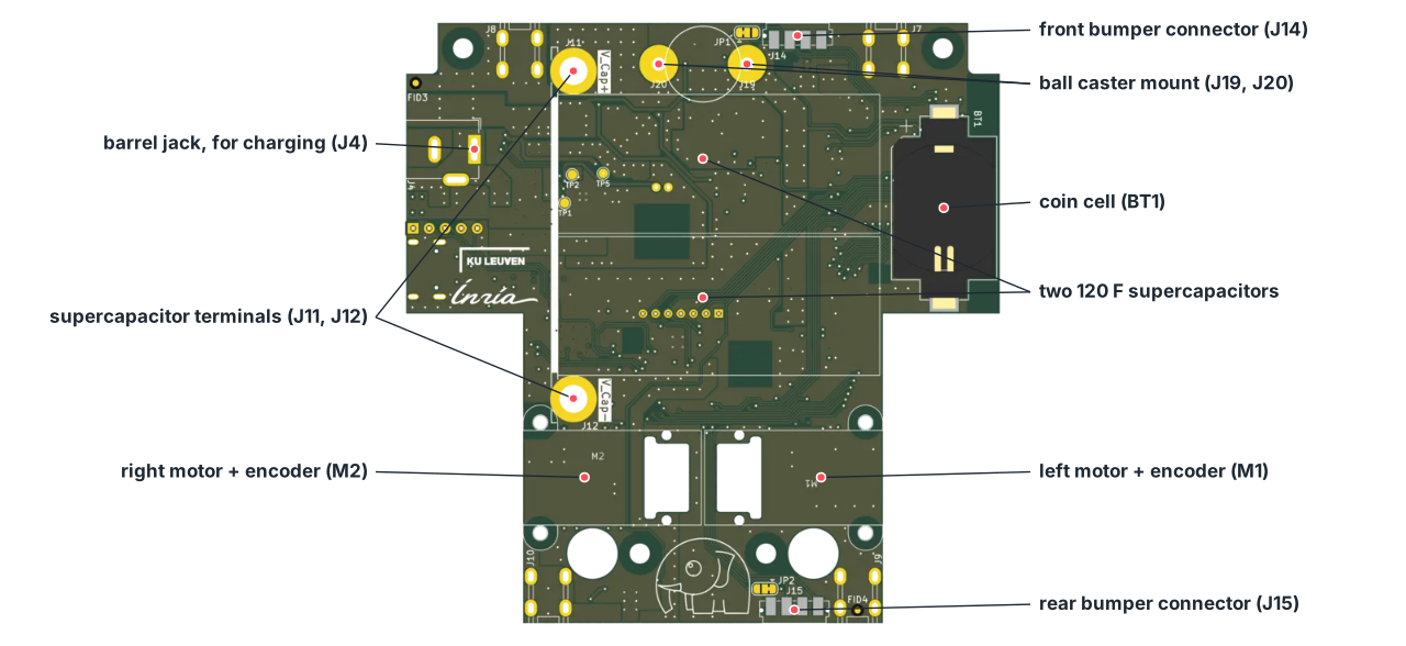
| Energy | two 120 F supercapacitors, no battery |
| Charging | about 30 s to full, from the barrel jack or the charging station |
| Running time | about 1 h in typical use, about 20 min driving non-stop at full speed |
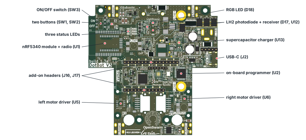
| On and off | the ON/OFF switch (SW3) at the left edge of the top side; switching OFF also discharges the supercapacitors through a 4.7 Ω resistor, so a robot that is off holds no stored energy |
| Processor and radio | nRF5340: two Arm Cortex-M33 cores and a 2.4 GHz Bluetooth LE radio, which runs Mari |
| Position | a Lighthouse 2 photodiode and receiver on top |
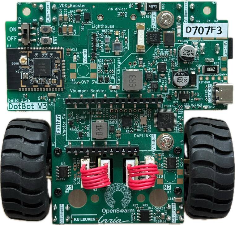
Figure 2 and Figure 3 label the board’s two sides, rendered from the board design files (build 1.3a); each dot is the documented position of the part. Figure 4 and Figure 5 are photos of a real robot, from an earlier build (1.2a), so a few small parts differ.
Datasheets. The DotBot v3 schematic (PDF), the nRF5340 product specification, the BQ24640 supercapacitor charger, and the TPS61021A and TPS61022 boost converters.